

TI Museum
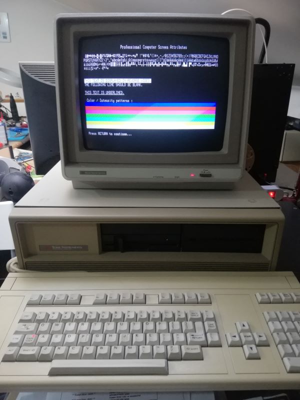
 Model: Professional Computer (PC) Color Version
Adapter: 110 volt or 220 volt (Italy)
Year: 1983
Keyboard: QWERTY full-stroke keyboard with arrow keys and separated numeric keypad
Cpu: Intel 8086 Speed: 5 mhz CO-processor: 8087 Ram: 64k (up to 768k) Sound: Beeper
Text mode: 80 x 25 Graphics mode: 720 x 300
Size - Weight: 47 x 42 x 19 cm / 12 kg with monochrome monitor / 14 kg with the color monitor
I/O ports: Parallel/Centronics port, 5 expansion slots (non IBM compatible), 4 x serial ports
Media: two 5''1/4 disk-drive (320k) OS: MS-DOS 2.1 CP/M 86, UCSD P-system, Prologue and Concurrent CP/M 86.
Peripherals: 10Mb or 20Mb hard-drive ( need interface), RAM expansion cards, Voice recognition card, Ethernet card.
Price: 64k model about 3000$ (USA, november 1983) / 64k model : £ 4.000.000 (Italy, 1985)
Info: The TIPC is very similar to the IBM PC both architecturally and from a user-experience perspective, with some technically superior aspects.It is based on the Intel 8088 CPU and an optional Intel 8087 floating point coprocessor. It supports MS-DOS compatible operating systems,but is not a fully IBM PCcompatible computer. Alternative operating systems are CP/M-86, Concurrent CP/M-86, and the UCSD p-System. The TIPC was reviewed in Byte magazine in its December 1983 issue. The CPU clocked at 5 MHz (a bit faster than the 4.77 MHz of the IBM PC) and has 64 KB of RAM pre-installed. A RAM board can be installed in an expansion slot providing an additional 192 KB or RAM, for a maximum of 256 KB. A later version supports up to 768 KB of total memory. The computer featured 5 expansion slots and has either a 12-inch green-phosphor monochrome (CRT) monitor or a 12-inch color monitor with a color graphics resolution of 720x300 pixels. For text, the display shows 25 lines of 80 columns each. The device has a 5¼-inch floppy disk drive and can support a second floppy drive or a "Winchester" hard drive without requiring the use of an expansion slot or separate chassis, and typically features one of each.
Troubleshooting
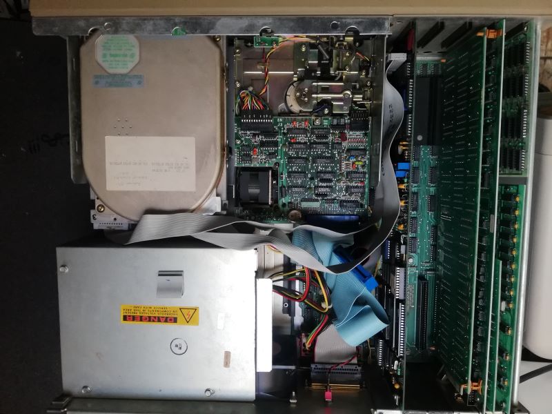
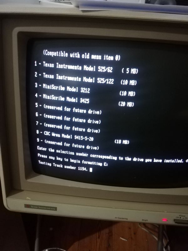 For this TIPC we used a Seagate ST225 (20 mByte) to be formatted with option 4 (miniscribe 3425). One thing that takes you back in time is the wship.com command from DOS 2.13 that allows you to park the HD heads.
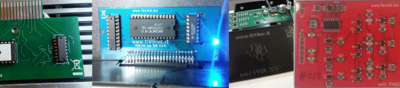
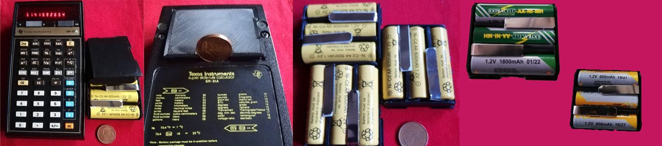
![]() As for the floppy we used this 360 kByte y53, as we have to repair the original one.
As for the floppy we used this 360 kByte y53, as we have to repair the original one.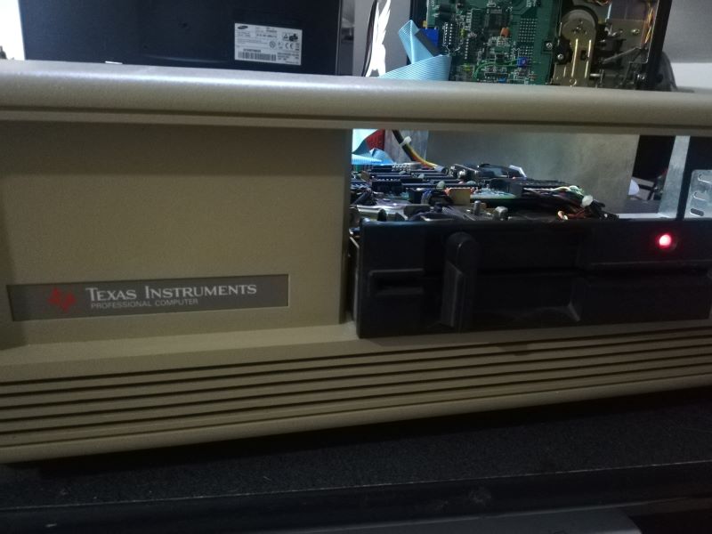
Library
![]()
![]()

Hardware Interface
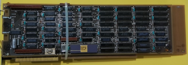
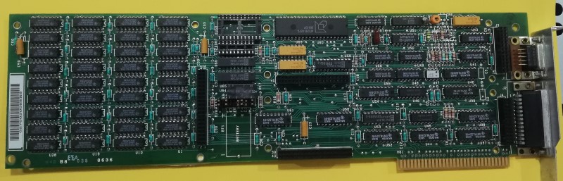
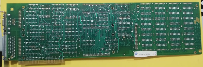
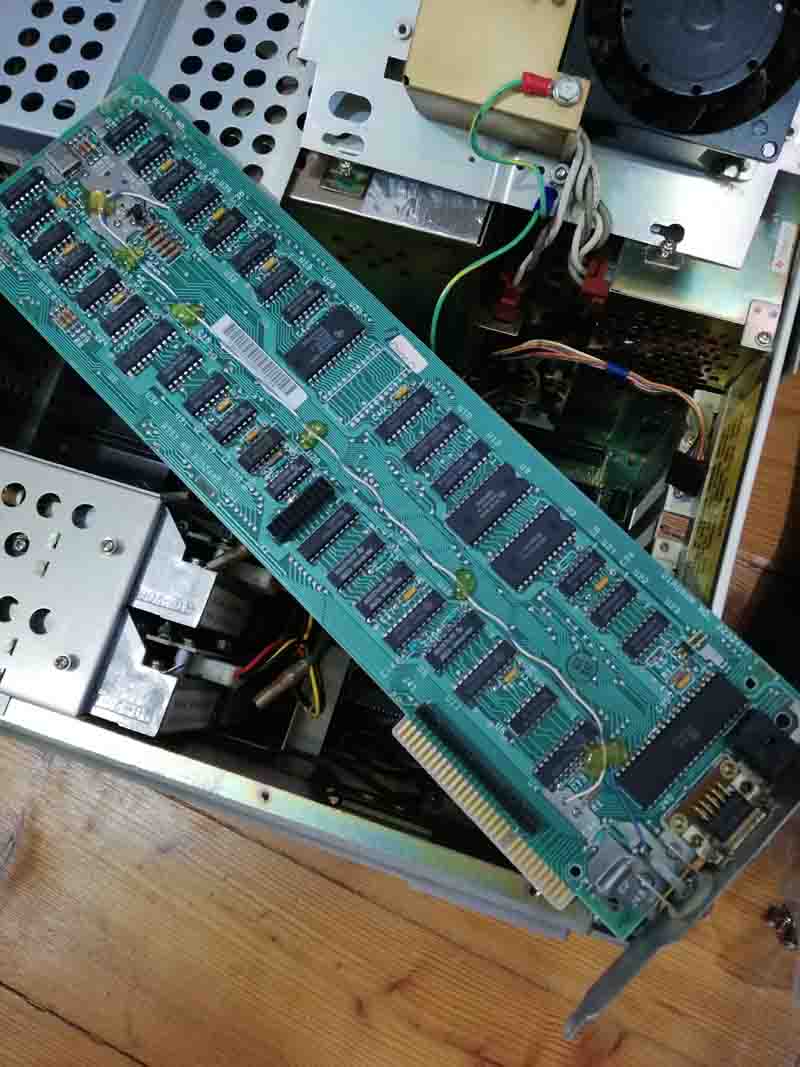
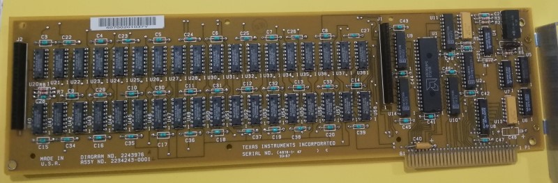 Model: Expansion RAM Card assy: 2234243-0001
Info:
![]()
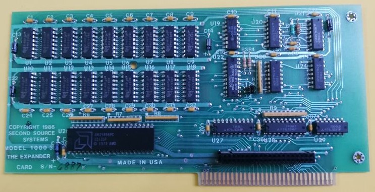
Model: Expander Card Second Source Mod.1000
Model: Second Source Mod. SP1100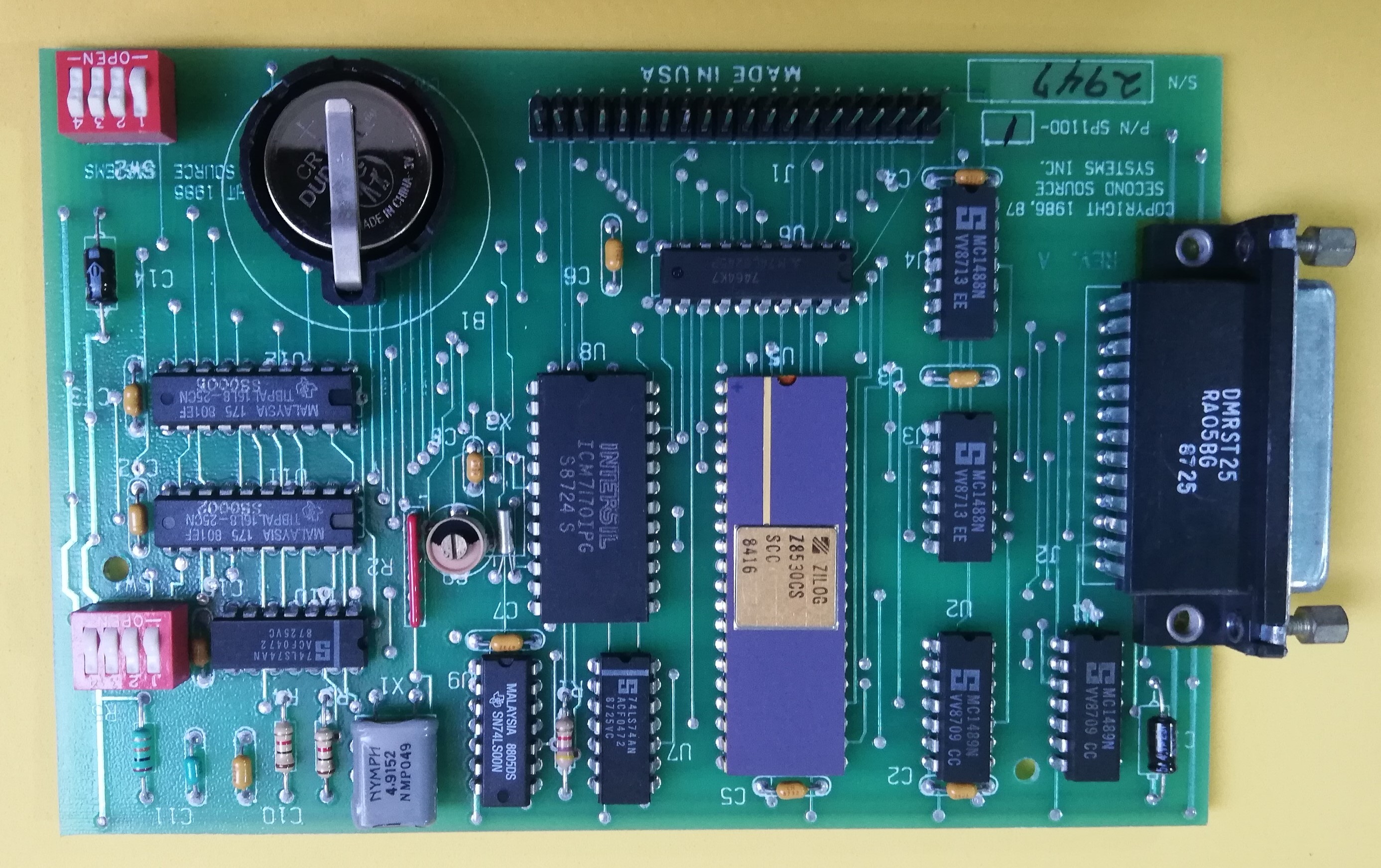
Info: This board is mounted in sandwich on the expander board, battery is BR2325
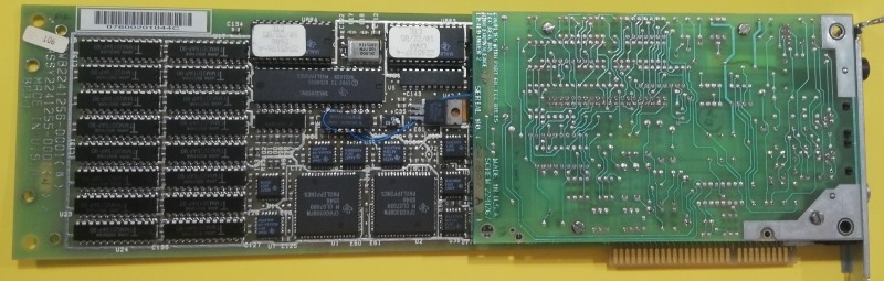
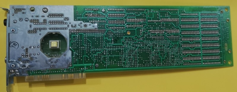
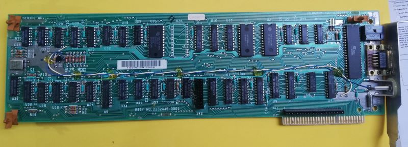 Model: Monochrome Graphics Video Controller assy:2232445-001
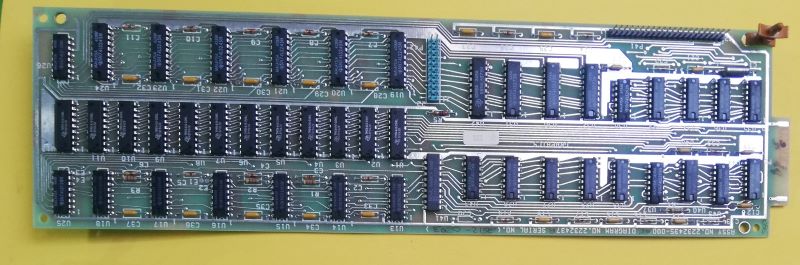
Model: Color Graphics Video Controller assy:2232435-000
Info: For monochromatic operation, only the monochromatic card is used; to have the color function it is necessary to insert the color card sandwiched on the monochromatic card.
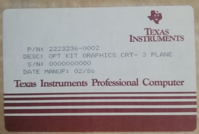
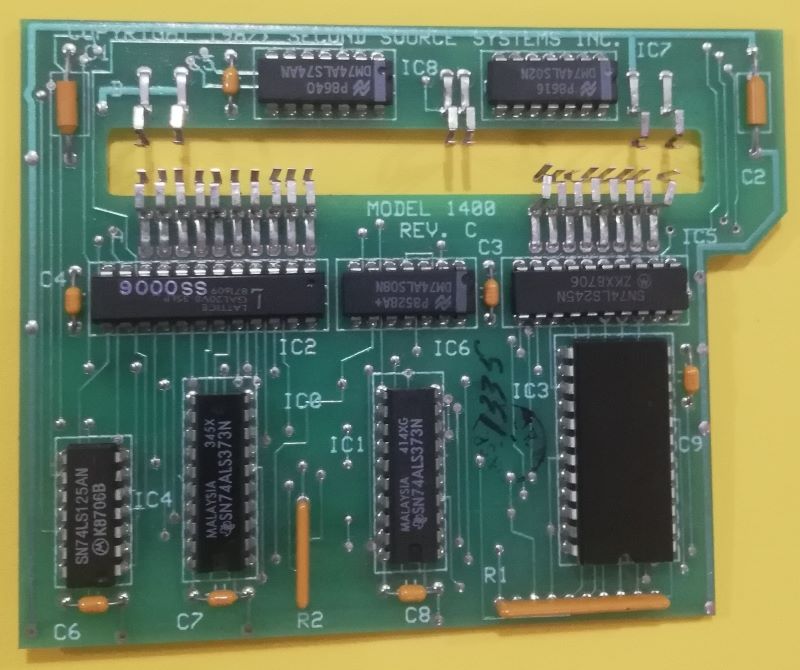 Model: IBM Graphics Emulator
Info:
![]()
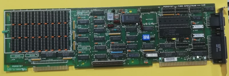 Model: The time Spectrume multifunction Board
Info:
![]()
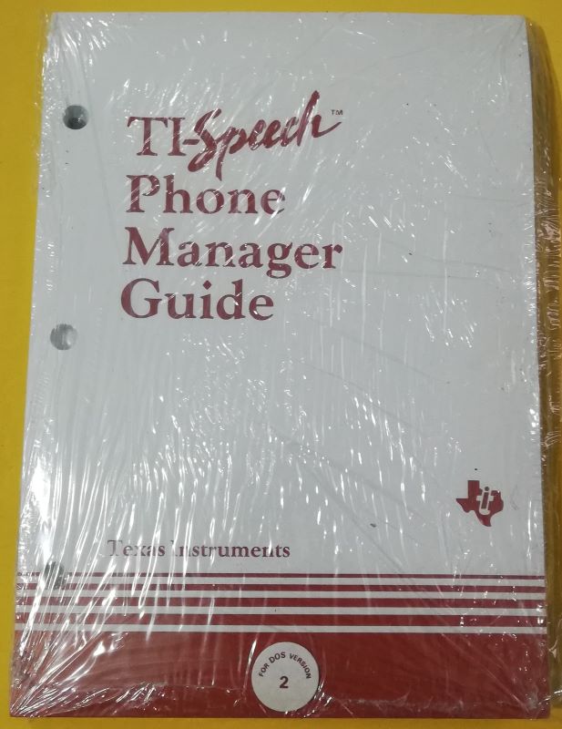
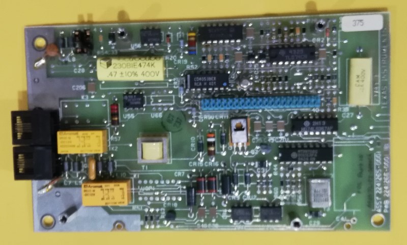
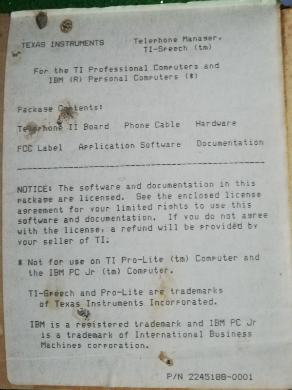
 Model: TI speech Phone Manager
Info:
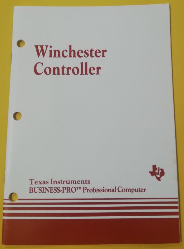
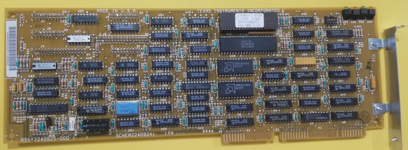 Model: Winchester Controller
Info:
![]()
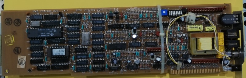
Model: Memory and clock assy: 2245876
Info: There is also a memory upgrade daughter board (256K Secondary Multi-Function Kit assy:2245895)
Model: Unidentified card
Info:
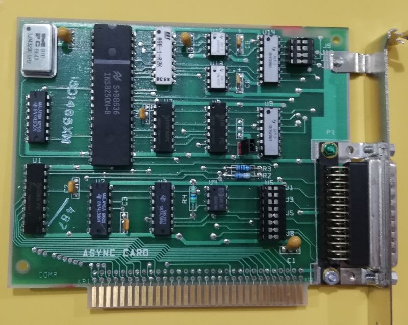
Model: Async Card
Info: I'm not sure if it can be used with the TIPC
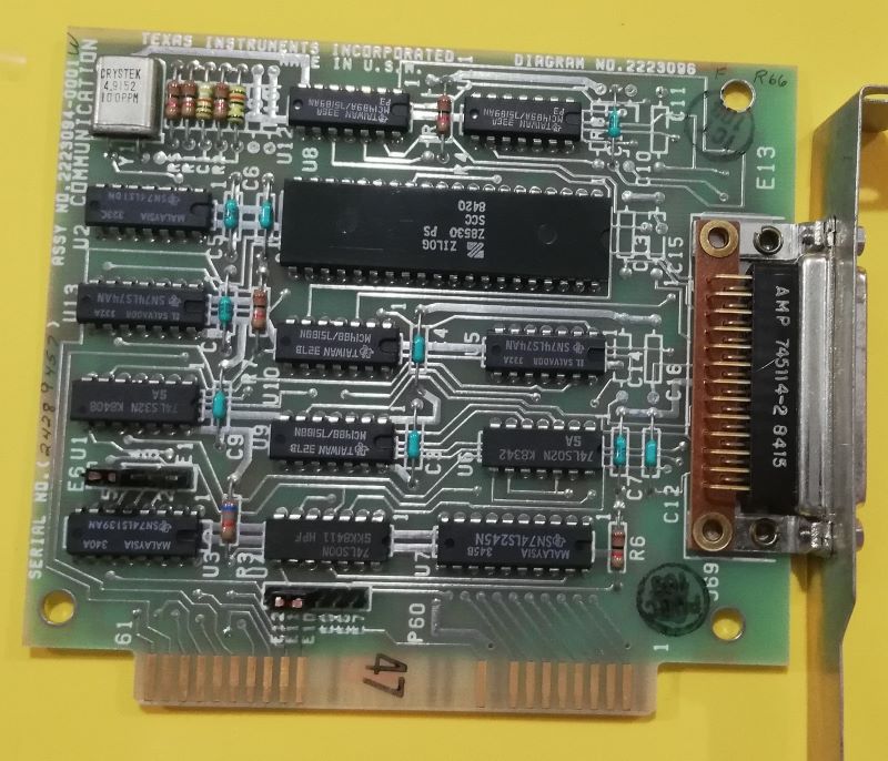
Model: Communication Card
Info: I'm not sure if it can be used with the TIPC
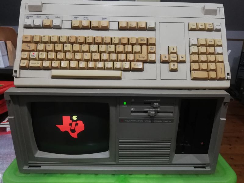 Model: Portable Professional Computer (PPC) Color Version
Adapter: 110 volt
Year: 1983
Keyboard: QWERTY full-stroke keyboard with arrow keys and separated numeric keypad
Cpu: Intel 8086 Speed: 5 mhz CO-processor: 8087
Ram: 64k (up to 768k) Sound: Beeper
Text mode: 80 x 25 Graphics mode: 720 x 300
Size - Weight: 47 x 42 x 19 cm / 12 kg with the monochrom monitor / 14 kg with the color monitor
I/O ports: Parallel/Centronics port, 5 expansion slots (non IBM compatible), 4 x serial ports
Media: two 5''1/4 disk-drive (320k)
OS: MS-DOS 2.1 CP/M 86, UCSD P-system, Prologue and Concurrent CP/M 86.
Peripherals: 10Mb or 20Mb hard-drive ( need interface), RAM expansion cards, Voice recognition card, Ethernet card.
Price: 64k model about 3000$ (USA, november 1983) / 64k model : £ 4.000.000 (Italy, 1985)
TroubleShooting
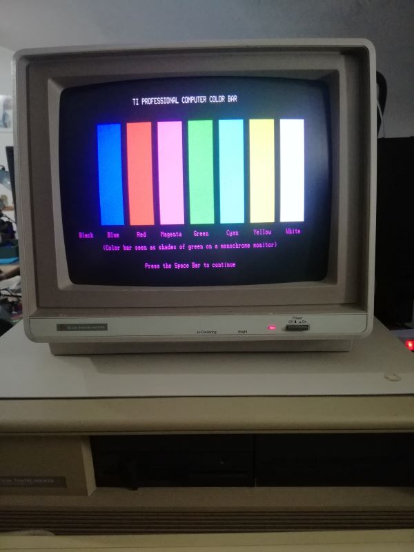
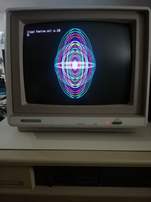
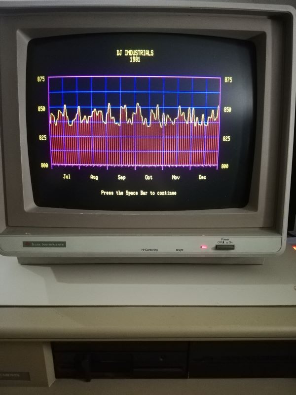
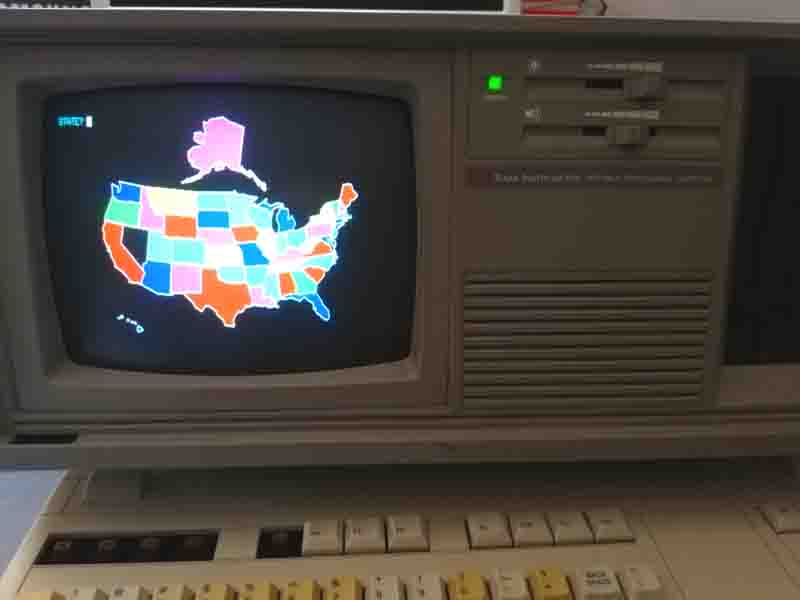
Video Tests
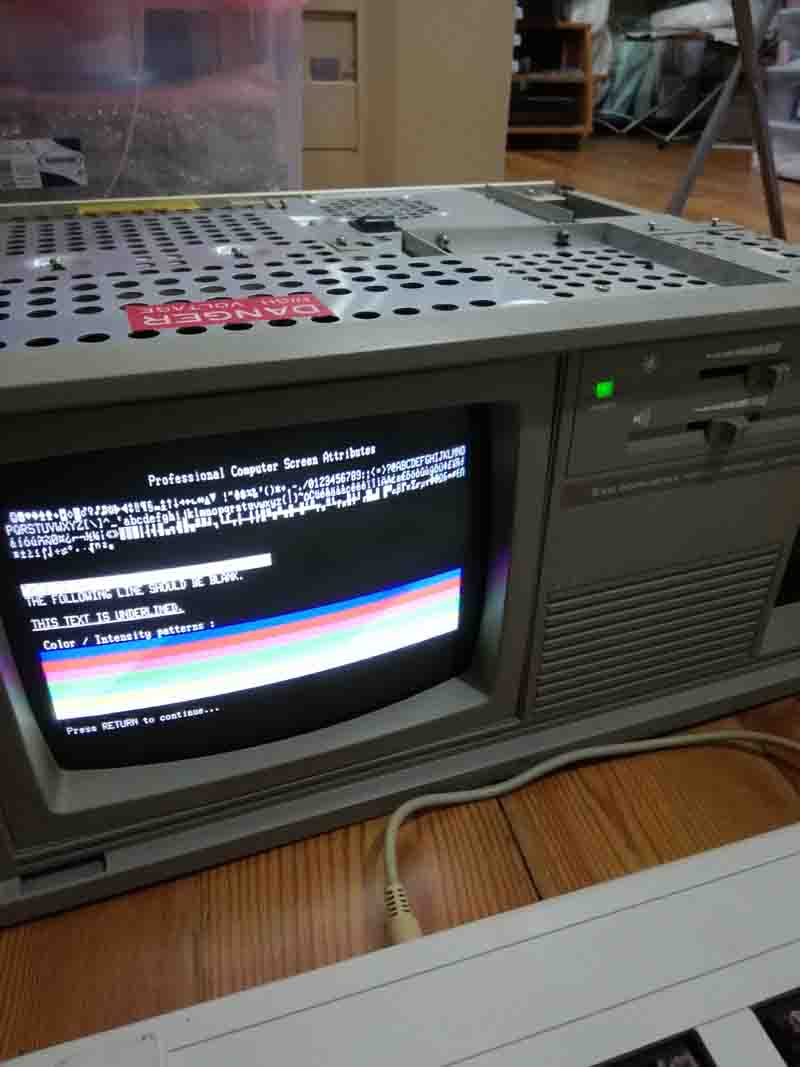
 Here you can see some video card tests.
Here we tell you about some necessary repairs after the mother board broke, during the 2nd edition dedicated to Texas Instruments in the city of Rieti in 2023.
Mother Board broke
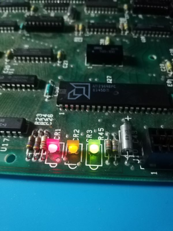
 The first thing to do in the event of a fault is to check the status of the three LEDs above the mother board CR1, CR2, CR3. Normal operation at boot is the switching on of all three and subsequently the switching on of the red, orange and solid green. In our case all three are turned on, the manual states that there is a block in reading the EPROMs.
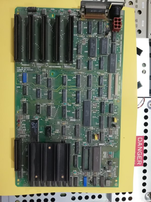
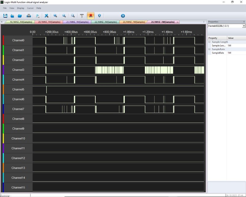
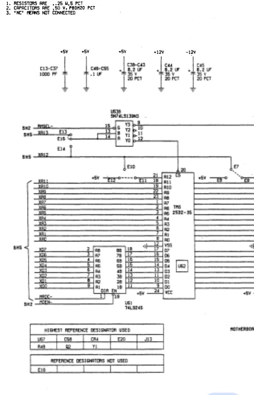 We started investigating both with the oscilloscope and with a logic analyzer, we concentrated on reading the data and in particular on U61.
![]()
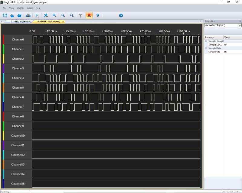 We noticed that on the EPROM side and on the U61 (74LS245) bus transceiver side, the data was not moving. After replacement, the mother board works again
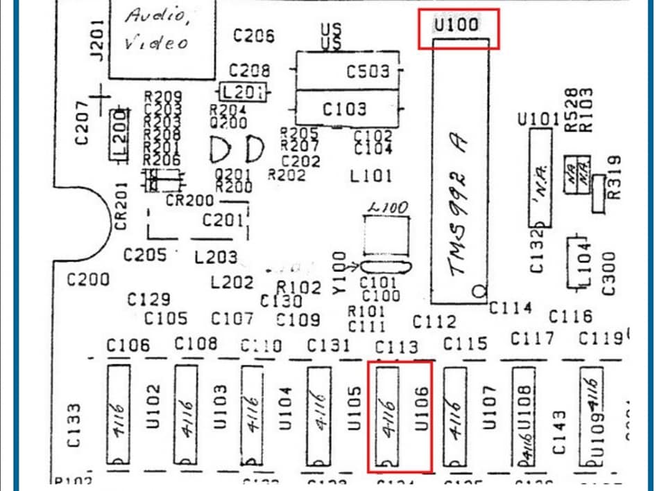
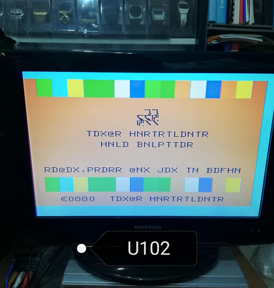
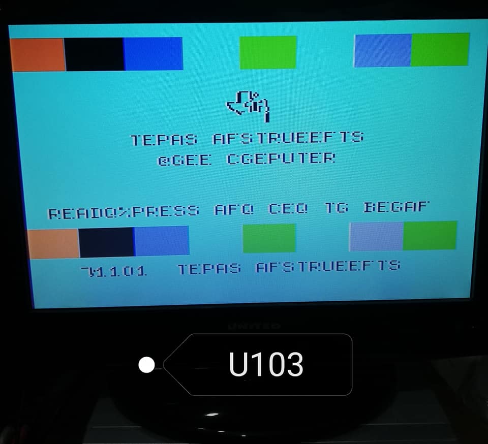
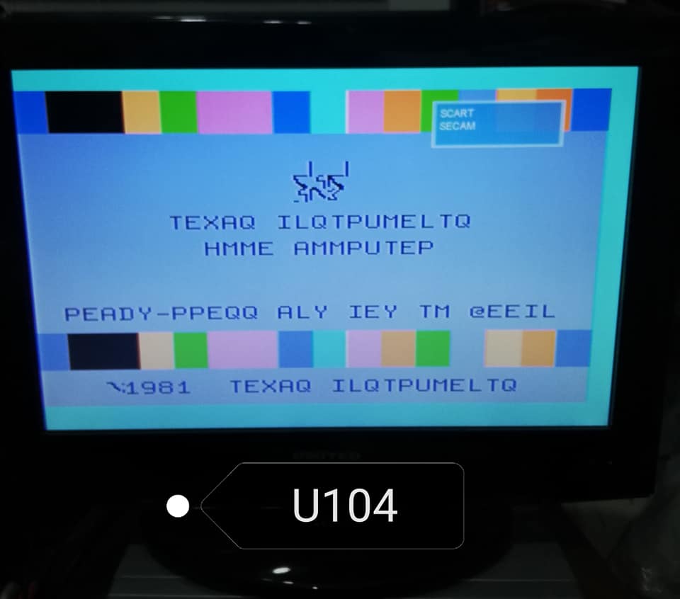
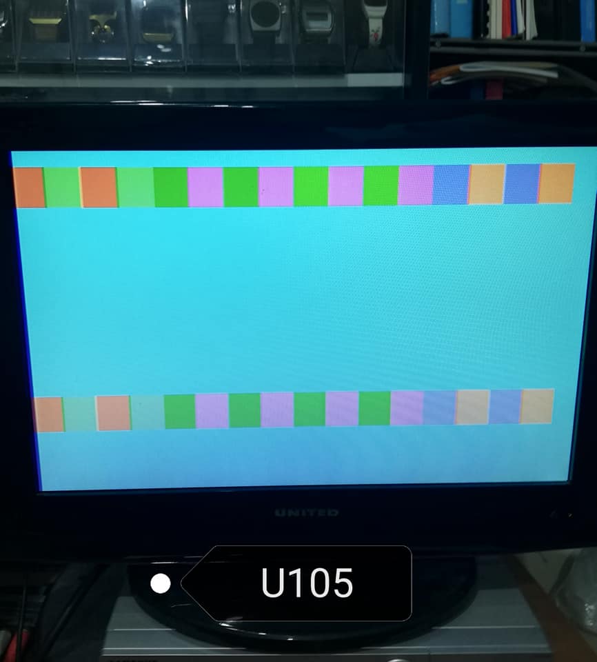
VDP RAM wrong
If you have a problem with the 4116 video RAM and you don't have the oscilloscope, you can basically use these photos to find the faulty RAM. This help is useful if one of the RAMs has the DOUT pin locked (broken ram).
 Wiring diagram.
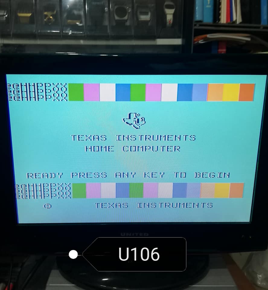
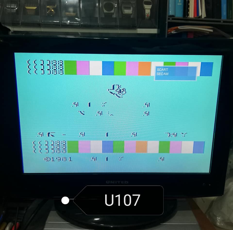
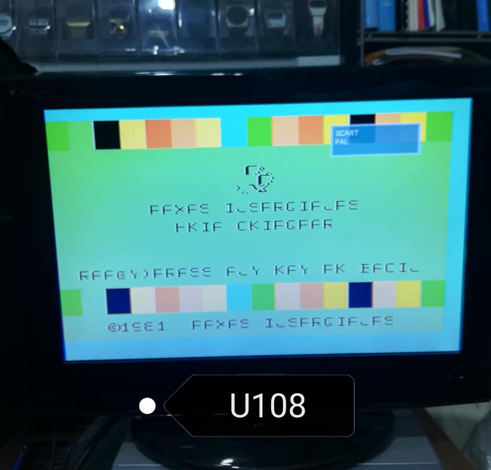
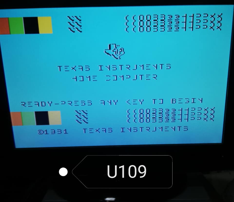
The videoprocessor use in the TI-99/4A comes in three flavors, that differ uniquely by the kind of output signal they send to the monitor port.
The TMS9918A issues a 525-lines, NTSC signal for US television format.
The TMS9928A issues a 525-line signal, in the form of a B&W luminance/sync signal and two color differential signals. This is meant to drive a RGB monitor, with a minimal external circuitery.
The TMS9929A issues a 625-line signal, in the same format as the 9928A. It is meant for use with the european PAL system.
CONSOLE DEBUGGING HELP
By John Guion
Dallas TI Home Computer Group
PROBLEM AREAS
1) Console will not power up
&TI-99/4A &Console &and &Peripheral &Expansion &System &Technical &Data manual available from Texas Instruments' Dealer Parts Department [(806) 741-2265] will serve as an excellent source for schematics and part location guide.
The information contained herein is only intended for use as a reference for possible debugging procedures. It is not intended as a repair guide for the common user with little or no knowledge of digital electronics or the basic structure of the TI-99/4A system. The author assumes no responsibility for damages resulting from improper use of this information.
This information should only be reproduced in its entirety with credit to the original author.
1 CONSOLE WILL NOT POWER UP
1.1 General information.
Failure of the TI-99/4A console to power up and produce the TI title screen is a common problem that is also the hardest to track down and fix since failure of nearly any component in the console or power supply can cause this.
The following are not intended as solutions to the problem, but merely as points to check that may aid in finding the actual problem and fixing it.
Unless a particular part is suspected, replace any socketed chips possible with known working equivalents before de-soldering any components. Since the socketed chips are common causes of lock up, eliminating them as possible problems first may save excess soldering on the board. The console will power up if the sound chip is removed entirely, but not if that chip is shorted internally.
A simple TTL logic probe can be used for tracing signals in the circuit. An oscilloscope may also be used and has the advantage of being able to check clock signals for proper frequency. When a signal should exist as an output from a particular device, be sure to check that device's input for proper signals before attempting to replace the component. When checking for locked up signals, try to trace all signals back through the circuit to the point of origin. A set of schematics (available from several sources, including TI) will help greatly in this part of debugging.
Tracing locked signals can determine whether or not the signal is missing due to a faulty component that it must pass through or what power up operation was occurring during lock up.
1.2 Console power up procedure.
A. TMS9900 CPU resets and addresses low ROM locations.
B. TMS9900 initializes.
C. TMS9900 sets up workspace registers in MCM6810 RAM.
D. TMS9900 begins GROM read.
E. TMS9900 enters delay loop for about 1/4 second.
F. TMS9919 sound chip is disabled.
G. TMS9918A VDP chip is initialized.
H. 4116 VDP RAM is initialized (requires about 1 second).
I. Title screen is loaded into VDP.
J. TMS9919 sound chip emits beep.
K. TMS9900 CPU enters keyboard scan.
L. System is ready for use.
1.3 Voltage/signal checklist.
A. Check power supply for +5V, +12V, and -5V. Lack of -5V often results in a grey flickering screen on power up.
Check for +5V on chips throughout board.
Check TMS9900 for -5V at pin^1; +5V at pins^2, 33, 59, and 64; and +12V at pin^27. If any voltages are missing, check for shorts on main board. Replace power supply if necessary.
B. Check TMS9900 pins^8, 9, 25, and 28 for clock signal. If not found, check TIM9904 clock generator pins^1, 2, 3, and 4 for clock signal. If not found, check TIM9904 supply voltages (+5V at pin^20, +12V at pin^13), crystal, and tank circuit. If no external problem can be found, possible TIM9904 failure.
C. Check TMS9918A pin^39 and pin^40 for the 10.73863 MHz clock. If missing, check crystal and oscillator circuit. Otherwise, check TMS9918A pin^36 and pin^37 for clock outputs. If not found, remove GROMs and sound processor (located next to GROMs) and test again for clock. If missing, possible TMS9918A failure. Reinsert GROMs and sound processor after tests.
D. Check TMS9918A pins^14 (-CSW) and^15(-CSR) for lock up. If locked up, check memory enable from pin^6 of 74LS32 and pin^13 of 74LS138 located next to MCM6810. Trace signal to find possible failure.
E. Check TMS9918A pin^13 (MODE) for lock up. If locked up, trace signal back to TMS9900. Also check for other components that may be locking up this line (it is used as A14). If no other fault can be found on that line, possible TMS9918A failure.
F. Check TMS9918A pin^1 (-RAS), pin^2 (-CAS), and pin^11 (-R/W) for lock up. If locked up, possible TMS9918A failure.
G. Check TMS9918A pins^17 through 24 (data lines) for signals. If missing, trace to fault. Possible TMS9918A or TMS9900 failure.
H. Check TMS9918A pins^3 through 10 (RAM address/data lines) for signals. If missing, possible TMS9918A failure.
I. Check 4116 RAM pin^14 (DATA OUT) on each chip for signal. Each chip missing signal may be at fault as well as TMS9918A.
J. Check TMS9900 pin^62 (READY) for lock up. If locked up, check TMS9900 pin^6 (-RESET) for signal. If pin^6 is locked up low, possible TIM9904 failure. If high, possible TMS9900 failure. If TMS9900 pin^6 is not locked up, trace circuit back from pin^62 to find fault.
K. Check all three GROMs (CD2155, CD2156, and CD2157) at pin^10 (-CS) and pin^15 (GREADY) for signals. If either is missing, remove all three GROMs and test pin^10 again for signal. If the signal at pin^10 does not exist, trace back through circuit to find failure. If signal exists, replace GROMs one at a time until GROM that causes lock up on pin^15 is found.
L. Check all three GROMs for signal on pin^11 (M0/A14) and pin^12 (M1/DBIN). If missing, trace circuit to find break in signal path.
M. Check each GROM for -5V at pin^14, +5V at pin^9, and -.8V to -.6V at pin^16. If missing, check for broken trace. If -.8V/-.6V is missing or at
-5V, check diode connected to that line.
N. Remove sound generator. If console powers up, check pin^16 for +5V, pin^4 for clock from TMS9918A, pin^5 (-WE) for signal, and pin^6 (-CS) for signal from 74LS138 closest to MCM6810. If these signals exist, possible sound chip failure.
O. Check TMS9918A pin^36 for composite video output. If missing, check TMS9918A crystal and clock circuit and pin^16 (-INT) for interrupt signal. If signals exist, possible TMS9918A failure.
P. Check GROMs for clock on pin^13. If missing, check clock output on TMS9918A pin^37. If signal on TMS9918A exists, check for break in signal path. If not, check TMS9918A oscillator circuit. If oscillator operates, possible TMS9918A failure.
Q. Check pin^20 (-CS) of console ROMs for lockup. If locked up, trace circuit back to find fault.
R. Check pins^7 and 9 through 15 of 74LS138 nearest I/O port to determine memory area accessed during lock up. Check pin^4 (-MEMEN) for lock up. If no signal can be found on pin^7 or pins^9 through 15, possible 74LS138 failure.
S. Check pin^11 (-CS) of MCM6810 RAMs for lock up. If locked up, trace circuit back to find fault.
T. Check TMS9901 pin^5 (-CE) for lock up. If locked up, check 74LS138 nearest I/O port for failure. Check TMS9901 pin^11, 17, and 18 for lock up. If locked up, trace circuit back to find fault.


